Les guides pour les nuls
Index- Frames of Reference (FOR)
- Rotational Kinematics
- Coriolis Theorem
- Inertia Tensors
- Lagrangian Mechanics
- Hamiltonian Mechanics
Frames of Reference (FOR)
Colloquially, FORs simply denote different “perspectives”. FORs differ from one another in their origin and set of basis vectors. Classic aerospace FORs may include
- Body fixed FOR
- Inertial FOR
- Wind FOR
It is important to distinguish the difference between a FOR and a coordinate system: coordinate systems are different ways to express an object with respect to a certain FOR.
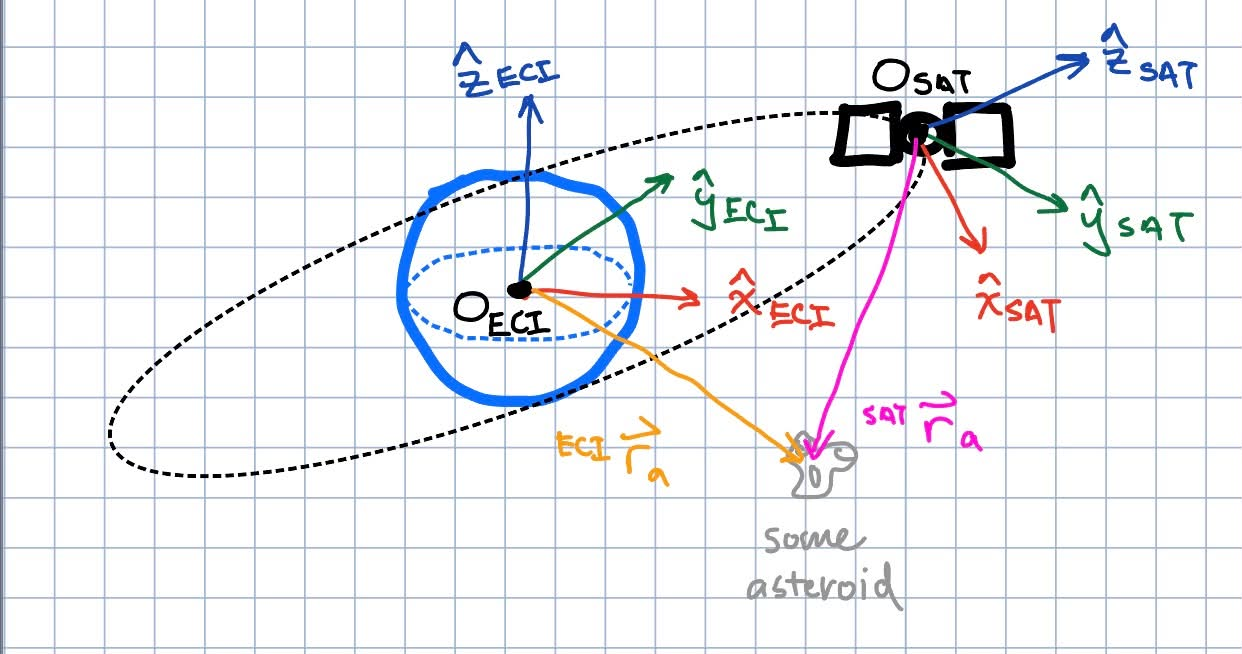
In this figure of a satellite orbiting earth, there are two FORs: one centered on earth and the other centered and moving with the satellite (denoted $ECI$ and $SAT$ respectively). A stray asteroid is also in orbit, and its position $\vec{r}_a$ can be expressed EITHER in $^{ECI}\vec{r}_a$ or $^{SAT}\vec{r}_a$. However, each of these vectors can be expressed in, for instance, cartesian, polar, or spherical coordinate systems wrt their FOR.
Rotational Kinematics
There is a fantastic resource from various faculty/alumni of the UC Berkeley Mechanical Engineering Department that covers everything and more of what I am going to hastily summarize about rotations: [https://rotations.berkeley.edu/site-information/]. Additionally Arman Golroudbari also offers a strong resource: [https://armanasq.github.io/tag/attitude/]
Rotational motion and attitude is nonlinear and more complex than translational motion. Scope is narrowed to rotation only.
We start the different attitude coordinate systems. In the same way that we are able to say an object “translated” by $a$ units in $\hat{x}$, $b$ units in $\hat{y}$, and $c$ units in $\hat{z}$, these are ways to express a rotated orientation in order of increasing usefulness. all frames of reference are implied to be orthonormal cartesian.
Active vs Passive Rotations
Before covering the various attitude representations, it is important to semantically establish what an Active vs a Passive rotation is.
- Active rotations rotate the rigid body about a fixed coordinate system
- Passive rotations rotate the coordinate system and keep the rigid body fixed.
It is super important to define which of these 2 systems you are working with. In general, you will see that active vs passive rotations will determine whether you are using
- Positive or negative for Euler Angles ($[\phi, \theta, \psi]$ or $[-\phi, -\theta, -\psi]$)
- Tranpose or original of rotation matrix ($R$ or $R^T$)
- The conjugate or the original of your quaternion ($a + bi + cj + dk$ or $a - bi -cj - dk$).
In aerospace, it is far more common to use passive rotations in order express vectors wrt an inertial frame. In computer graphics for example, it is far more common to use active rotations for the GPU tp render what an object looks like after being rotated from the perspective of the user. I use passive convention.
Attitude Representations
Euler Angles
Euler Angles are the most intuitive way to describe rotation. They are fantastic for human comprehension (the colloquial usage of “Yaw”, “Pitch”, and “Roll” are Euler Angles), but under the hood it is almost never a good idea to use euler angles.
Euler angles express any object attitude as a series of rotations about 3 axes from its initial orientation. This seems sensible; 3 numbers to describe an orientation in 3D is minimal and efficient, but there are pitfalls to this approach. An Euler coordinate usually looks something like $[\phi, \theta, \psi]^T$, where each value represents an angle-rotation about an axis. But many questions of conventions are begged of this.
Intrinsic vs Extrinsic Euler Angles
- Intrinsic Euler Angles represent rotations about the body FOR. This convention is represented by $X-Y’-Z’’$. Where the $’$ and $’’$ makes clear that you are rotating about a derived FOR.
- Extrinsic EAs are the opposite and represent rotations about a fixed inertial FOR regardless of the current attitude of the rigid body. This convention looks more like $X-Y-Z$ where $’$s are not necessary.
The conversion between intrinsic and extrinsic rotations is a simple matter of order reversal.
\[\begin{bmatrix} \phi \\ \theta \\ \psi \end{bmatrix}_{X - Y' - Z''} = \begin{bmatrix} \psi \\ \theta \\ \phi \end{bmatrix}_{Z - Y - X}\]This conversion is deceptively simple. Realize that an intrinsic ACTIVE/PASSIVE rotation is the NOT the same as an extrinsic PASSIVE/ACTIVE rotation. Instead, a rigorous proof is needed, thanks to robit on mathstackexchange: [https://math.stackexchange.com/questions/1137745/proof-of-the-extrinsic-to-intrinsic-rotation-transform]
Non-commutativity
One of the pitfalls of Euler Angles is its non-commutativity. $X(\phi)-Y(\theta)-Z(\psi) \neq Y(\theta)-Z(\psi)-X(\phi) \neq Z(\psi)-X(\phi)-Y(\theta) …$. This is a blanket rule that applies without loss of generality to intrinsic/extrinsic Euler/Tait-Bryan angles.
Generally, all rotational compositions (chains of rotations) are non-commutative, but at least with rotation matrices and quaternions, a single attitude can be expressed by a single mathematical object, whereas for Euler Angles, an attitude requires particular attention to the terms WITHIN the form of expression. Just one more annoying thing to keep track of.
Proper Euler vs Tait-Bryan Angles
Proper Euler Angles follow the convention $A-B-A$ (extrinsic) or $A-B’-A’’$ (intrinsic), where the first and last axes are the same. Tait-Bryan Angles follow the convention $A-B-C$ (extrinsic) or $A-B’-C’’$ (intrinsic) where all three axes are unique.
In total, there are 24 possible Euler-Angle conventions (another reason why they suck). There are a total of 6 permutations of Euler Angles and 6 permutations of Tait-Bryan Angles. Then, each permutation can also be expressed in intrinsic or extrinsic conventions.
Singularities
The single most damning offense of Euler-Angles comes in the form of its singularities. Colloquially, this is also called gimbal-lock. Every Euler Angle convention has a certain rotation about the 2nd axis that causes loss of a degree of freedom. To show this, here’s an example that segways nicely into the next section on Rotation Matrices.
This is the composed matrix of a $Z(\psi)-Y’(\theta)-X’’(\phi)$ or equivalently $X(\phi)-Y(\theta)-Z(\psi)$ rotations. \(\mathbf{R}(\psi, \theta, \phi) = \begin{bmatrix} \cos\psi\cos\theta & \cos\psi\sin\theta\sin\phi - \sin\psi\cos\phi & \cos\psi\sin\theta\cos\phi + \sin\psi\sin\phi \\ \sin\psi\cos\theta & \sin\psi\sin\theta\sin\phi + \cos\psi\cos\phi & \sin\psi\sin\theta\cos\phi - \cos\psi\sin\phi \\ -\sin\theta & \cos\theta\sin\phi & \cos\theta\cos\phi \end{bmatrix}\) If $\theta = 90^o$, the composed rotation matrix breaks down into \(\begin{align*} % Directly substituting sin(90°) = 1 and cos(90°) = 0 \mathbf{R}(\psi, 90^\circ, \phi) &= \begin{bmatrix} 0 & \cos\psi\sin\phi - \sin\psi\cos\phi & \cos\psi\cos\phi + \sin\psi\sin\phi \\ 0 & \sin\psi\sin\phi + \cos\psi\cos\phi & \sin\psi\cos\phi - \cos\psi\sin\phi \\ -1 & 0 & 0 \end{bmatrix} \\ % Simplified using trigonometric angle subtraction identity \Delta = \phi - \psi &= \begin{bmatrix} 0 & \sin(\phi - \psi) & \cos(\phi - \psi) \\ 0 & \cos(\phi - \psi) & -\sin(\phi - \psi) \\ -1 & 0 & 0 \end{bmatrix} \end{align*}\) Where what was originally 2 independent rotation angles $\phi$ and $\psi$ has degenerated into one single angle $(\phi-\psi)$.
Key conclusions:
- All Classic Euler Angle conventions have a singularity at $0^o$ and $180^o$
- All Tait Bryan Angle conventions have a singularity at $\pm 90^o$
avoiding these singularities is exactly why we created new attitude coordinates.
Rotation Matrices
Rotation matrices use 9 values to encode a 3-D attitude, a bit inefficient. All rotation matrices $Q$ live in a special lie algebra set $Q \in SO(3)$ (special orthoganol 3). This implies 3 properties.
- 3x3 real matrix
- $Q^TQ = I$. aka $Q$ is orthoganol, $Q^T = Q^{-1}$
- $\det(Q) = 1$. aka $Q$ does not scale vectors
Keeping in mind that I use passive rotations, the rotation matrices about the principal axes are the following:
\[Q_x(\theta) = \begin{pmatrix} 1 & 0 & 0 \\ 0 & \cos\theta & \sin\theta \\ 0 & -\sin\theta & \cos\theta \end{pmatrix} \quad ; \quad Q_y(\theta) = \begin{pmatrix} \cos\theta & 0 & -\sin\theta \\ 0 & 1 & 0 \\ \sin\theta & 0 & \cos\theta \end{pmatrix} \quad ; \quad Q_z(\theta) = \begin{pmatrix} \cos\theta & \sin\theta & 0 \\ -\sin\theta & \cos\theta & 0 \\ 0 & 0 & 1 \end{pmatrix}\]It is straightforward to use these to create compositions of rotations about the principal axes, with particular attention to left-multiplication order.
Direction Cosine Matrices
Often in academia researchers like to call rotation matrices direction cosine matrices (DCM) instead. They accomplish the exact same thing - expressing attitudes in a 3x3 matrix. However the way DCMs are constructed differ from the sequential composition of rotation matrices, and instead start by assuming you have the basis vectors of your starting and ending FORs already.
Recall that $a \cdot b = \lvert a \rvert \lvert b \rvert \cos{\theta_{ab}}$ and for unit vectors $a \cdot b = \cos{\theta_{ab}}$. An inertial FOR $I$ is defined by a set of 3 unit basis vectors $[\mathbf{e_1, e_2, e_3}]$. A body FOR $B$ also has 3 unit basis vectors $[\mathbf{b_1, b_2, b_3}]_I$ where here the subscript $I$ denotes that $\mathbf{b_j}$ are expressed wrt $I$. We can use these to construct the DCM.
\[\mathbf{DCM}_{BI} = \begin{bmatrix} \mathbf{b}_{1} \cdot \mathbf{e}_1 & \mathbf{b}_1 \cdot \mathbf{e}_2 & \mathbf{b}_1 \cdot \mathbf{e}_3 \\ \mathbf{b}_2 \cdot \mathbf{e}_1 & \mathbf{b}_2 \cdot \mathbf{e}_2 & \mathbf{b}_2 \cdot \mathbf{e}_3 \\ \mathbf{b}_3 \cdot \mathbf{e}_1 & \mathbf{b}_3 \cdot \mathbf{e}_2 & \mathbf{b}_3 \cdot \mathbf{e}_3 \end{bmatrix} = \begin{bmatrix} \mathbf{b_1}^T \\ \mathbf{b_2}^T \\ \mathbf{b_3}^T \end{bmatrix} = \begin{bmatrix} \mathbf{e_1}_B & \mathbf{e_2}_B & \mathbf{e_3}_B \end{bmatrix}\\ = \begin{bmatrix} \cos(\theta_{11}) & \cos(\theta_{12}) & \cos(\theta_{13}) \\ \cos(\theta_{21}) & \cos(\theta_{22}) & \cos(\theta_{23}) \\ \cos(\theta_{31}) & \cos(\theta_{32}) & \cos(\theta_{33}) \end{bmatrix}\]Where $\mathbf{DCM}_{BI}$ is left-applied to vector $x_I$ like so.
\[x_B = [\mathbf{DCM}_{BI}] x_I\]There are a few things worth pointing out about the structure of the $\mathbf{DCM}_{BI}$
- Its rows are the body frame basis expressed in the inertial frame
- Its columns are the inertial frame vectors expressed in the body frame
- it is still $\in SO(3)$.
- Applying $\mathbf{DCM}{BI}$ to a vector wrt $I$ effectively projects that vector onto all three basis vectors of $B$. Similarly if working with $\mathbf{DCM}{IB} = \mathbf{DCM}{BI}’$ applying to a vector wrt $B$ effectively projects that vector onto all three basis vectors of $I$. This makes it clear how $\mathbf{DCM}{BI}$ works.
Quaternions
Quaternions are an initially counterintuitive, 4-dimensional complex mathematical object that are standard practice when it comes to actually expressing attitudes in real aerospace or computer graphics systems.
Quaternions look like $a + bi + cj + dk$ where
- $a$ is the real part
- $i, j, k$ are ALL imaginary numbers
- $b, c, d$ are the respective components of the imaginary numbers
The fundamental structure behind a quaternion that makes it so useful for attitude representations is expressed most succinctly as
- $ijk = -1$
- $ij = k$; $jk = i$; $ki = j$
- $ji = -k$; $kj = -i$; $ik = -j$
- $ii = jj = kk = -1$
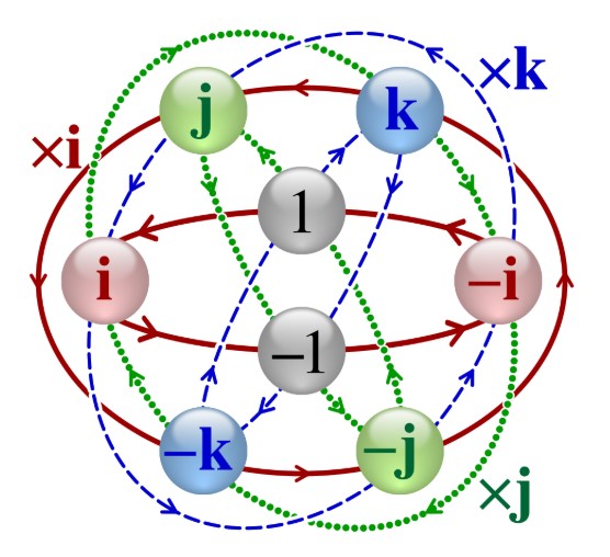
People really like throwing this graphic around just to visualize the 6 inherent cycles contained within this mathematical structure, but I personally think it is quite a useless graphic that attempts to visually depict a concept where visualization contributes nil to deeper understanding.
Hamiltonian vs JPL (Shuster) convention
Before we go ANY further with quaternions, I must quickly mention that one of the most annoying yet critical aspects behind using a quaternion depends on whether you are using Hamiltonian or Shuster convention. What I showed above is Hamiltonian convention, the more common of the two. Shuster (JPL) convention flips the direction of all the arrows not connected to the $1$ and $-1$ nodes.
Explicitly, Shuster convention uses
- $ijk = 1$
- $ij = -k$; $jk = -i$; $ki = -j$
- $ji = k$; $kj = i$; $ik = j$
maybe one day in the future I explain why this JPL convention exists
Quaternion Math
Application to vectors
Conversions
Kinematics
How do we translate a $\dot{Q}, \dot{q}, [\dot{\phi}, \dot{\theta}, \dot{\psi}] \rightarrow \omega$?